DRAGON'S LAIR / SPACE ACE PCB SOUND VOLUME CONTROL
Written by Shaun Wood - 13 September 2002
INTRODUCTION
While playing Dragon's Lair or Space Ace, the joystick and button input is accompanied by sound effects generated by a sound
chip on the main PCB. The volume of these sounds is fixed. Most of these games are now located in private homes, and
the sound level may be much louder than necessary. This document will show you step-by-step instructions to add a control to
the main board to adjust the volume of the sound effects. Upon completion, you will be able to adjust the volume in a range
from zero to 150% of normal (200% with optional resistor).
PARTS AND TOOLS NEEDED
- 1K Potentiometer
- 3.3K resistor (optional)
- Soldering Iron
- Solder
- Vacuum de-soldering tool (recommended)
- Wire
- Two-pin in-line connector (optional - method 2)
THEORY OF OPERATION
U19 is a General Instruments AY-3-8910 sound chip. Its three independent analog
channels are tied together on pins 3, 4, and 38. This output signal is then controlled by a small network of resistors and
capacitors (schematic page 2, grids B3 and B4). R3 provides impedance matching. C17 bleeds away any high frequency
noise. C18 is a DC blocking capacitor. Resistors R20 and R21 form a voltage divider circuit providing the fixed volume
setting. The AC signal across R21 is passed through C18 to the right amplifier U29.
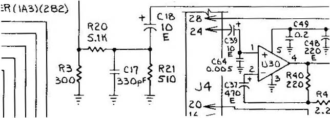
It is the ratio of R21 to the total resistance which determines the volume level.
In the factory setting:
Signal out = Signal in * R21 / ( R21 + R20 ) = Signal in * 510/ (510 + 5100)
Signal out = Signal in * .091
A little more than 9% of the original signal is amplified.
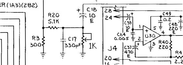
To make the volume adjustable, we need to replace R21 with a 1K variable resistor. With this VR adjusted to zero ohms, the
signal out is zero. With the VR set at 1000 ohms:
Signal out = Signal in * VR / ( VR + R20 ) = Signal in * 1000/ (1000 + 5100)
Signal out = Signal in * .164
A little more than 16% of the original signal will be amplified.
Option: If your primary interest is to increase the volume of the sound effects, then you can also replace R20 with a 3.3K
resistor. Along with the VR, you will achieve a maximum output signal of 23%.
CONSTRUCTION
Method 1 - Mounted on the board:
(Click on the pictures for a larger view.)
For this method, your potentiometer should be a board-mount miniature type with the middle (adjustable) lead forward from the other two.
- Desolder and remove resistor R21.
- Fill the hole nearer to the middle of the board with solder to close it.
- Use a vacuum de-soldering tool to remove any remaining solder and open the hole nearer the edge of the board.
- Align the middle lead of the potentiometer over the open hole, and with a felt tip marker, mark the points on the fringe of the circuit board for the other two leads.
- Verify that the marked points are over the unused edge of the board and not over any circuit tracings.
- Use a 1/16" bit to drill the holes.
- Insert the potentiometer, and solder the middle lead.
- Solder a wire from ground to one of the side leads.
- Solder a small wire from the middle lead to the remaining side lead.
- Set the pot to the mid-point and reassemble your board.
Method 2 - Full size potentiometer to be mounted with the other volume controls:
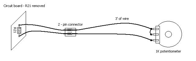
- Desolder and remove resistor R21.
- Using lightweight speaker wire (or equivalent), solder two wires into the holes from R21.
- Solder the other ends of the two wires to the two outside leads on the potentiometer.
- Solder a small jumper wire from one of the side leads to the middle lead.
- Option - Install a two-pin in-line connector a few inches from the board. This will allow for easy removal of the board while leaving the volume control in place.
- Reassemble the circuit board.
- On the volume-control mounting bracket, drill the appropriate sized hole and mount your potentiometer.
WARNING: If the two-pin connector is disconnected during boot-up, 100% of the sound signal will be supplied to the audio amplifier.
DISCLAIMER
You are responsible for all work you decide to do on your game. Neither I nor the Dragon's Lair Project are responsible if you damage your
equipment. Follow this guide at your own risk.
HOME
| LASER GAMES |
LASER COMMUNITY
| TECH CENTER
Questions? Comments? Problems? CONTACT US
dragons-lair-project.com was created by Jeff Kinder & Dave Hallock, 1997 - 2025.
All trademarks and copyrighted materials are property of their respective owners.