|
|
||
|
|
||
|
|
||
|
|
||
|
|
![]()
DRAGON'S LAIR / SPACE ACE PCB CONVERSION BETWEEN PR-7820 &
LD-V1000 - 20 March 2000 - Updated 20 March 2021
Written by Jeff Kulczycki - Photos by Roy Bailey
NOTE: This conversion is needed for a Dragon's Lair / Space Ace PCB
configured for the PR-7820 laserdisc player to be able to use an actual
LD-V1000 laserdisc player.
This conversion is not needed for the installation of an aftermarket laserdisc player conversion/replacement product, which works
with a PCB configured for the PR-7820.
INTRODUCTION
Early Dragon's Lair games used the Pioneer PR-7820 laserdisc player. Plagued with problems, this player was later replaced with the Pioneer LD-V1000 and a revised logic board. This document will show you the steps for converting your PR-7820 boardset to work with the LD-V1000, or vice versa, as well as an in-depth look at how the two laserdisc players communicate with the logic board.
PARTS NEEDED
DOCUMENTS REFERENCED THROUGHOUT
THEORY OF OPERATION
LASERDISC PLAYER COMMANDS - The command sets for the two players are similar.
The PR-7820 commands can be found in APPENDIX A on page 21 of the PR-7820 PROGRAMMING REFERENCE GUIDE.
The LD-V1000 commands can be found in Figure 5 on pages 10-11 of the LD-V1000 INTERFACE GUIDE.
Both charts are consolidated in the following table:
Command LD-V1000 PR-7820 LOAD CC CC DISPLAY DISABLE CD -- DISPLAY ENABLE CE -- GET FRAME NO. C2 -- GET 2ND DISPLAY C3 -- GET 1ST DISPLAY C4 -- TRANSFER MEMORY C8 -- X 0 FORWARD (STOP) A0 -- X 1/4 FORWARD A1 -- X 1/2 FORWARD A2 -- X 1 FORWARD A3 -- X 2 FORWARD A4 -- X 3 FORWARD A5 -- X 4 FORWARD A6 -- X 5 FORWARD A7 --
Command LD-V1000 PR-7820 SKIP FORWARD 10 B1 -- SKIP FORWARD 20 B2 -- SKIP FORWARD 30 B3 -- SKIP FORWARD 40 B4 -- SKIP FORWARD 50 B5 -- SKIP FORWARD 60 B6 -- SKIP FORWARD 70 B7 -- SKIP FORWARD 80 B8 -- SKIP FORWARD 90 B9 -- SKIP FORWARD 100 BA -- CLEAR BF -- 0 3F 3F 1 0F 0F 2 8F 8F 3 4F 4F
Command LD-V1000 PR-7820 4 2F 2F 5 AF AF 6 6F 6F 7 1F 1F 8 9F 9F 9 5F 5F STORE F5 F5 RECALL 7F 7F DISPLAY F1 F1 AUDIO 1 F4 F4 AUDIO 2 FC FC PLAY FD FD STOP FB FB AUTOSTOP F3 F3 SEARCH F7 F7
Command LD-V1000 PR-7820 SCAN FWD F0 -- SCAN REV F8 -- STEP FWD F6 F6 STEP REV FE FE REJECT F9 F9 NO ENTRY FF -- BRANCH -- CF DEC REG -- F0 HALT -- BF INPUT -- F8 SLOW REV -- FA NULL -- 00 SLOW FWD -- F2 The main difference control-wise between these two players is the way they communicate on the bus. The PR-7820 only has a one-way communication bus. It can receive Command Codes, but it cannot return any Status Codes. The LD-V1000, on the other hand, has a two-way communication bus. It can receive Command Codes, and it can return Status Codes. Figure 10 on page 19 of the LD-V1000 INTERFACE GUIDE lists all possible Status Codes that the LD-V1000 can return. Status feedback from the laserdisc player is important because the game needs to know when a SEARCH Command has finished. Once a SEARCH is finished, the game will send a PLAY command and allow the user to begin playing that scene.
The LD-V1000 indicates that the SEARCH has finished by returning the Status Code $D0 (SEARCH FINISHED). The PR-7820 indicates that the scene has been found by forcing the READY line low. It is this fundamental difference that requires that there be unique hardware and software for communicating to each of these players.
HARDWARE - The earliest version of the main PCB (80-12035-01) was designed to work only with the PR-7820. According to the DRAGON'S LAIR / SPACE ACE OPERATION AND MAINTENANCE MANUAL, this version has serial numbers below 6000. A later revision C PCB incorporates a change that allows the hardware to be configured to work with either the PR-7820 or the LD-V1000.
The hardware differences are summarized in the DRAGON'S LAIR / SPACE ACE OPERATION AND MAINTENANCE MANUAL as follows:
DISC PLAYER INTERFACE
The disc player interface is composed of U20, U21, and U16. In games with Pioneer 7820 disc players, U16 feeds both the ENTER+ and the INT/EXT signals to the disc player. The signal OUT DISC DATA+ at U16-5 is fed to the output enable pin at U21-1. U21 is used to send control words to the disc player. U20 is not used with the 7820. Games with 7820 players should have board serial numbers below 6000.
In games with the Pioneer LD-V1000 player, the only signal sent to the player from the Z80 is the INT/EXT signal generated at U16-9. The ENTER+ signal is returned from the disc player and is fed to U14-6. U16-5, the output disc data signal, goes high, disabling U21, when the Z80 wishes to read data words from the disc player via U20. Games with LD-V1000 players should have board serial numbers above 6000.
ADDITIONAL INFO - The schematics in the DRAGON'S LAIR / SPACE ACE OPERATION AND MAINTENANCE MANUAL label the interface signals differently than the laserdisc player manuals do. For clarity, the variances in the printed names of the signals are summarized in the table below.
Game Schematics PR-7820 Manual LD-V1000 Manual "READY" "READY" "COMMAND STROBE" "INT/ENT" "INT/EXT" "ENTER SIGNAL" "ENTER" "ENTER" "STATUS STROBE" The LD-V1000 INTERFACE GUIDE makes it clear that although the connectors are the same for both players, the hardware interface is not. You should not swap these players without making the proper hardware modifications. The guide offers the following warning:
WARNING: Although the Pioneer LD-V1000 and Pioneer PR-7820 series players use Amphenol type, 24-pin connectors, interfaces designed for the PR-7820 are not likely to be compatible with the LD-V1000 unless they have been suitably modified. Interfaces not specifically designed for the LD-V1000 Player may damage its output drivers.
The LD-V1000 INTERFACE GUIDE adds a brief tidbit in the INTERFACE PORT AND CONNECTIONS chart, Figure 1 on page 2, concerning the communication differences between the two players:
CONTACT # SIGNAL LINE DIRECTION 7 COMMAND STROBE Out of player 11 STATUS STROBE Out of player** 17 ENTER SIGNAL Into player*** ** Note: Directional change from PR-7820.
*** Note: Functional change from PR-7820.This chart and its footnotes show that the STATUS STROBE (ENTER on the schematic) comes out of the player when dealing with the LD-V1000 and goes into the player when dealing with the PR-7820. This explains the importance of the hardware change. The ENTER SIGNAL (INT/ENT on the schematic) is only a "Functional change" between the players, so it only requires a software change.
The PR-7820 PROGRAMMING REFERENCE GUIDE's only hint at how the PR-7820 communicates is on page 28. It states:
Commands entered via the External Computer Interface are interpreted exactly as if they had come from the RCU. The ENTER line acts like a "finger press" on a button...
The function of the ENTER line becomes more apparent below when analyzing the game's software.
ANALYZING THE SOFTWARE - The Dragon's Lair code itself gives the best information on how these two players are controlled. From analyzing the code, one can see that PR-7820 commands are sent out like this:
PR-7820 Command Output:
1) Force INT/EXT signal low
2) Place Command on bus
3) Set bus to output state
4) Force ENTER signal low
5) Delay
6) Return ENTER signal to high
7) Delay
8) Return bus to original stateYou can see here that the Command is placed on the bus and then the ENTER signal is toggled low for a short delay to act like a "finger press" on a control button.
PR-7820 Search Status:
1) Wait for READY signal to go lowThe PR-7820 sets the READY signal line low to indicate that it has finished executing the command.
LD-V1000 commands are sent out like this:LD-V1000 Command Output:
1) Place Command on bus
2) Wait for STATUS STROBE to go low
3) Wait for STATUS STROBE to go high
4) Set bus to output state
5) Force ENTER SIGNAL low
6) Wait for COMMAND STROBE to go low
7) Wait for COMMAND STROBE to go high
8) Return bus to original stateLD-V1000 Search Status:
1) Wait for STATUS STROBE to go low
2) Read Data from bus
3) Wait for STATUS STROBE to go highCommunication with the LD-V1000 is detailed on page 13 of the LD-V1000 INTERFACE GUIDE. The advantage of the LD-V1000 is that not only will it tell you when it has finished executing the command, it will also tell you if it was executed successfully or not. If the command failed, the software will attempt to send it again.
INSTRUCTIONS FOR THE PCB CONVERSION PROCESS
FOR NEWER PCB REVISIONS WITH THE W1 JUMPER PADS
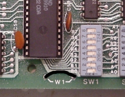
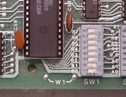
If you have a later revision PCB with a serial number above 6000, then you can easily configure the hardware to work with either player. Look on the edge of the PCB, near the DIP switches, for a jumper labeled W1. According to the MAGICOM MAIN LOGIC SCHEMATIC REVISIONS listed in APPENDIX D of the DRAGON'S LAIR / SPACE ACE OPERATION AND MAINTENANCE MANUAL:
Addition of Jumper W1, when installed, allows board to be used with Pioneer 7820 disc player with proper software.You should set jumper W1 according to the pictures below. A short piece of wire and a soldering iron should do the trick. Once you have the hardware jumper configured correctly, you'll need to read ahead and verify that you have the correct software and DIP switch settings.
(Click images for larger view)
W1 jumper set
for PR-7820W1 no jumper
for LD-V1000FOR EARLY PCBS BELOW SERIAL NUMBER 6000
If you have an early version of the PCB that only works with the PR-7820 and you wish to update it for use with the LD-V1000, then the changes are more involved. While there were many changes made to the hardware over time, not all of them are required to update the laserdisc player. Only the two changes needed to update the laserdisc player interface are shown below. Details about the other hardware changes and instructions for performing them are found on the Dragon's Lair v1 PCB Modifications page.
The CINEMATRONICS SERVICE BULLETIN NO. 84-2 has this to say about the two changes below:
The modification accomplishes two things. First, it rearranges the input to U-20 (74LS244). Secondly, it converts the ready line from an output to an input. The differences can be seen schematically by comparing the disc interface section of the revision E schematics and revision K schematics in your manual.
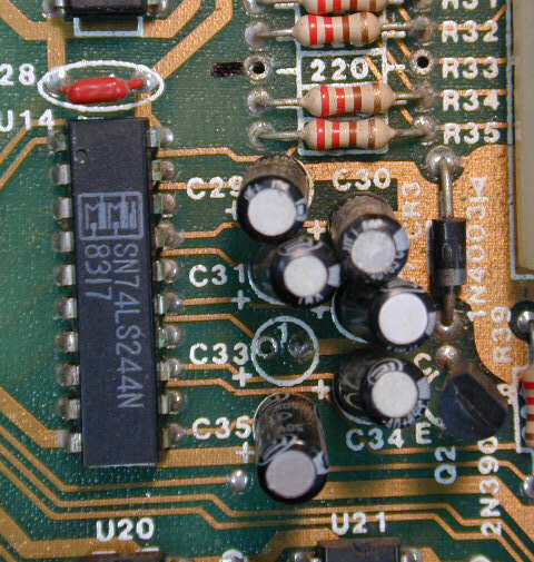
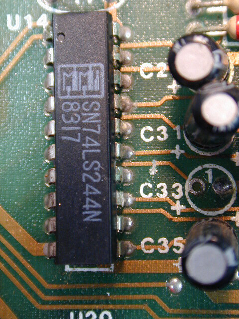
CHANGE #1 - Reroute the ENTER Signal - The first change that needs to be made is with the ENTER signal. For the PR-7820 it is required that the ENTER signal be an output from the game into the player. The signal comes out of U16 pin 6 (output IC) and goes to the PR-7820 via J1 pin 2. In order to use the LD-V1000, this signal must be changed to an input. The ENTER signal should be changed to enter via J1 pin 2 and feed into U14 pin 6 (input IC). The steps needed to accomplish this change are listed below.
(Click images for larger view)
1) Cut the trace out of U16 pin 6. 2) Remove R33 and C33. 3) Directly jumper a wire from J1 pin 2 to U14 pin 6. 4) Cut the trace coming out of U14 pin 6. It's interesting to note that the input signal that you will be replacing in steps 2 and 4 is the FAN input, which is not used. Removing R33 and C33 disables the FAN input.
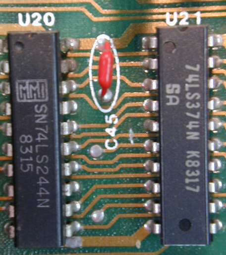
CHANGE #2 - Correct the U20 Pinout - The second change that you'll need to make is a correction for an error that was made in the PCB layout. The error was made on the pinout of U20, which is the IC responsible for returning the SEARCH data. The schematic does not show this error; it only exists on the PCB. Magicom fixed this error on revision J and included the following in the MAGICOM MAIN LOGIC SCHEMATIC REVISIONS listed in APPENDIX D of the DRAGON'S LAIR / SPACE ACE OPERATION AND MAINTENANCE MANUAL:
J. Correct pin out for inputs on U20 (74LS244) effective 9/16/83.The table below contrasts the erred pinning on U20 with what it should be, in reference to U21.
U21 U20 - was U20 - should be 5 6 4 6 17 6 9 13 8 15 15 13 16 8 15 19 4 17 (Click images for larger view)
Component Side
1 trace cut
to U20 pin 15
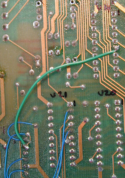
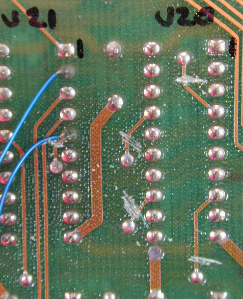
Solder Side
5 traces cut
to U20 pins 4, 8,
13, 17, U21 pin 5Solder Side
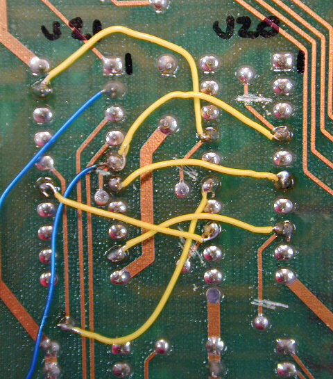
6 jumpers added
from U20 to U21
per table aboveYou can find a detailed drawing of the cuts and jumpers in the CINEMATRONICS SERVICE BULLETIN NO. 84-2. I highly recommend that you study revisions E and K of the main logic schematics in the DRAGON'S LAIR / SPACE ACE OPERATION AND MAINTENANCE MANUAL and become familiar with all the components and traces in the area that you will be modifying.
SOFTWARE CHANGE
Once your hardware is set up to use your player of choice, you must make sure that your software will work with that player as well. It is advised to use Dragon's Lair ROM revision F2, or Space Ace ROM revision A3, or the Enhancement ROMs, while making sure that your DIP switch setting for the laserdisc player model selection is correct per ROM revision.
DISCLAIMER
The user is solely responsible for any and all adverse effects resulting from the use or misuse of the information above.
HOME |
LASER GAMES | LASER COMMUNITY | TECH CENTER